Resources for Architects and Engineers
This page provides technical resources for architects and engineers working with pre-engineered metal buildings (PEMBs). Each section includes definitions, design variables, and structural systems, with images illustrating typical applications.
Building Specifications

Building Code
We design according to the International Building Code (IBC) and state or local requirements, updating regularly to reflect changes.

Snow Loads
Snow load requirements vary by region and elevation. Our buildings can be engineered to withstand light conditions of 5 psf or less, or heavy snow zones exceeding 200 psf. Proper snow load design ensures roof systems remain safe and functional throughout the building’s life.

Wind Loads
Wind speed ratings typically start at 90 mph but can be designed for areas requiring up to 200 mph. Proper design prevents uplift, racking, and lateral movement, protecting both structure and occupants.

Seismic Zones
Buildings in seismic zones must be designed to resist lateral forces caused by earthquakes. We engineer for stringent seismic criteria across the U.S., from California to the Mississippi fault line.
Design Variables

Building Width
The gable end of the building (endwall). We design buildings from 20′ wide up to 200′ clear span, or 600′ wide with interior columns.

Building Length
The sidewall dimension of the building. Structures can be designed from 15′ long up to 1000′ or more.

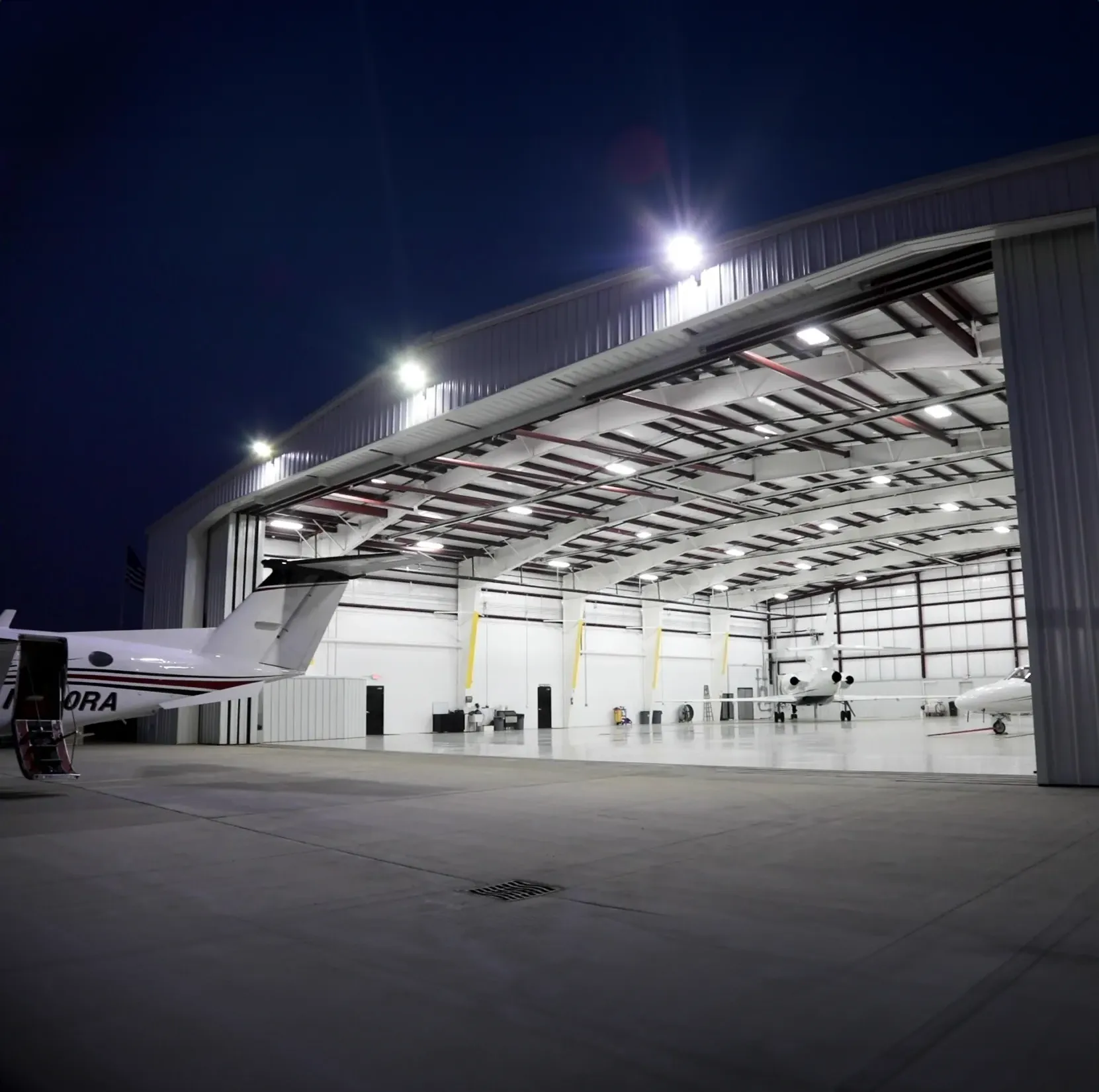
Eave Height
The vertical distance from the finished floor to the top of the eave strut. Minimum eave height is 10′, with designs available up to 60′+. Eave height often determines maximum door size.

Roof Slope
Expressed as rise over run (e.g., 2:12 means 2 inches rise for every 12 inches of run). Roof slopes affect peak height, drainage, and cost. We offer slopes from ¼:12 to 6:12+.

Bay Spacing
The distance between columns along endwalls and sidewalls. Typical ranges: 5′–30′ (endwalls), 20′–40′ (sidewalls). Wider spacing may reduce columns but increase girt sizes and costs.
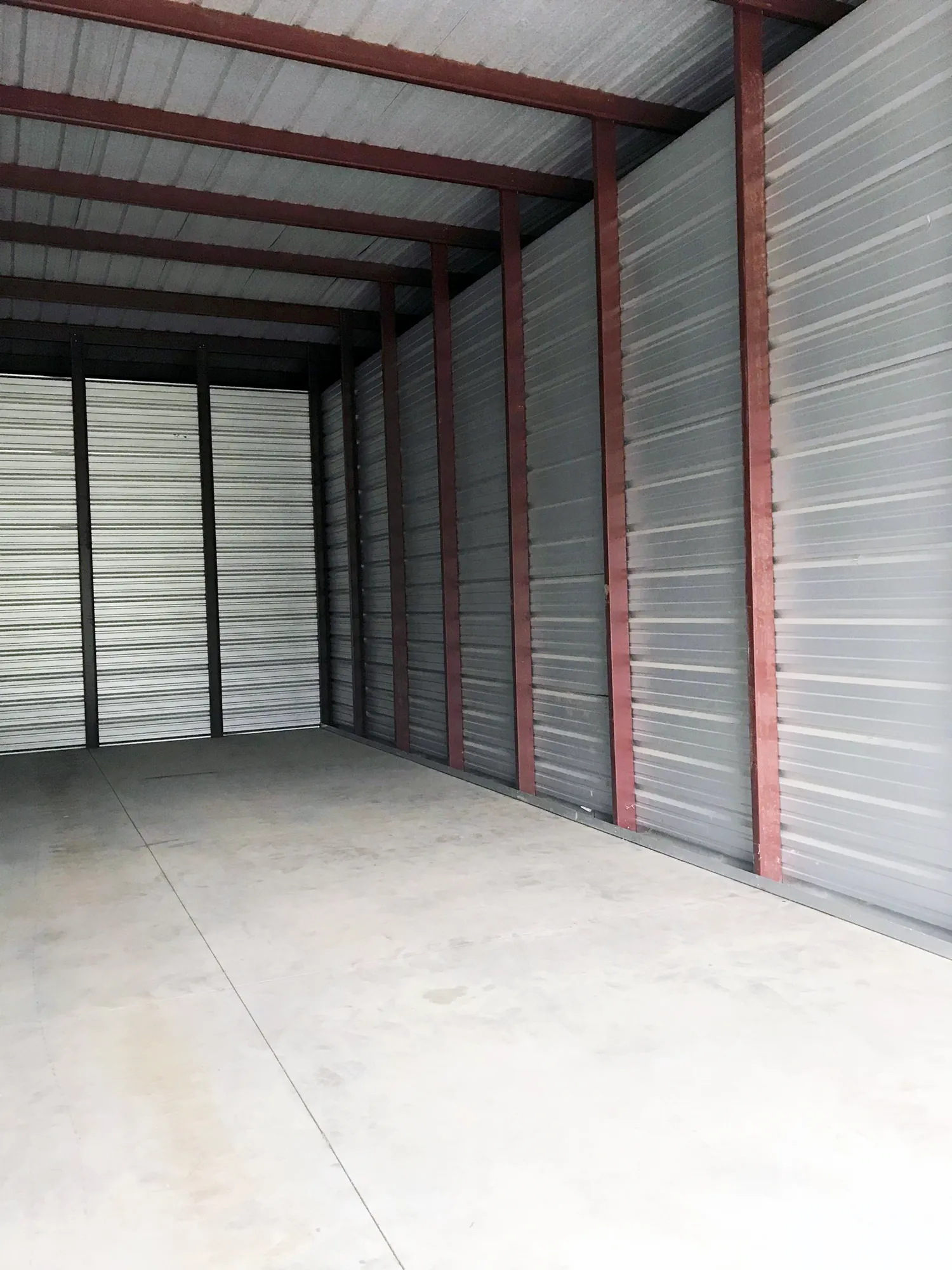
Framing Systems

Bearing Frames
A structural system of rafter beams supported by columns, commonly used at endwalls.

Expandable Frames
Designed to allow future building additions of the same width and height. Ideal for phased growth.

Non-Expandable Frames
Used where x-bracing is not permitted in the endwall. Also provides support for hangar door headers.
Straight Columns
Provide vertical sidewalls and are often used in buildings over 100′ wide for added strength.uakes. We engineer for stringent seismic criteria across the U.S., from California to the Mississippi fault line.
Tapered Columns
An economical design that narrows toward the top, reducing material use while maintaining strength.
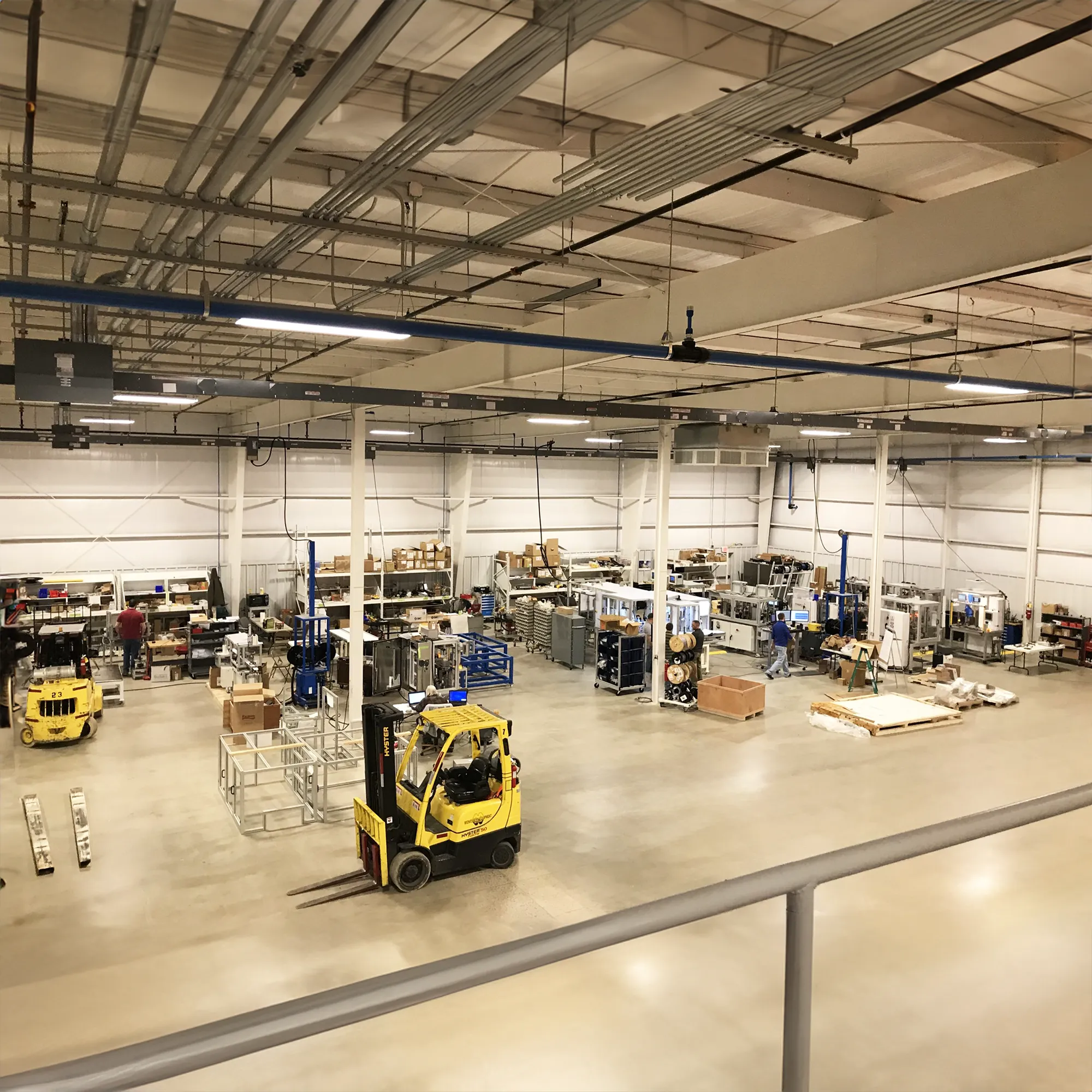
Interior Columns
Used in very wide buildings to reduce costs while supporting spans of 100′ or more.
Open Wall Conditions

Interior Columns
Used in very wide buildings to reduce costs while supporting spans of 100′ or more.
Bracing Systems

Rod Bracing
Used in very wide buildings to reduce costs while supporting spans of 100′ or more.

Cable Bracing
Used in very wide buildings to reduce costs while supporting spans of 100′ or more.

Angle Bracing
Used in very wide buildings to reduce costs while supporting spans of 100′ or more.
Color Charts


Your Next Building Starts Here
From aviation complexes to international projects, our custom steel buildings prove that the possibilities are endless. Tell us about your idea, and we'll engineer a building that makes it a reality.